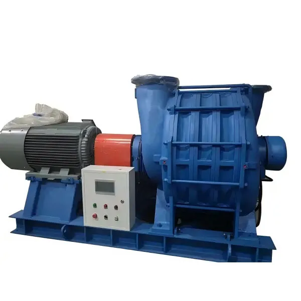
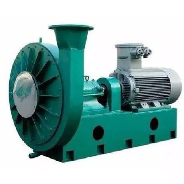
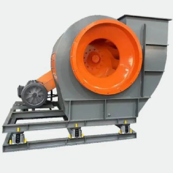
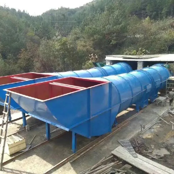
+86-13361597190
No. 180, Wujia Village Industrial Park, Nanjiao Town, Zhoucun District, Zibo City, Shandong Province, China
+86-13361597190
Boiler centrifugal induced draft fans are suitable for the draft systems of steam boilers ranging from 2 to 670 tons per hour in thermal power plants. The medium conveyed by the induced draft fan is flue gas, and the temperature must not exceed 250°C.
Boiler centrifugal induced draft fans are suitable for the draft systems of steam boilers ranging from 2 to 670 tons per hour in thermal power plants. The medium conveyed by the induced draft fan is flue gas, and the temperature must not exceed 250°C. Before the induced draft fan, a dust removal device must be installed; according to general power plant usage, the dust removal efficiency should not be less than 85%.
For conveying corrosive gases of certain concentrations, glass fiber or stainless steel materials can be used to manufacture corrosion-resistant fans. For conveying flammable and explosive gases, cast aluminum impellers and explosion-proof motors can be used to make explosion-proof fans. For gas conveyance at temperatures between 80°C and 250°C, water-lubricated bearing seats made of ordinary steel plates can be used, while for gases above 250°C, it is recommended to use stainless steel materials. As the temperature of the conveyed gas increases, the pressure of the fan will change accordingly, and the motor power may also need adjustment. For detailed information, please consult the manufacturer.
1) The induced draft fan is designed as a single suction type. Sizes range from No. 8 to No. 29.5.
2) Each type of fan can be manufactured in either left rotation or right rotation forms.
3) The outlet position of the fan is indicated by the angle of the casing's exit.
4) The drive methods include: B, C types for belt drive; D type for coupling drive; E, F types for belt drive.
5) An example of the full product name is as follows:
G4-73No.20DRight45 degrees
Y4-73No.20DLeft90 degrees
Where G and Y represent boiler supply fans and boiler induced draft fans respectively.
Centrifugal fan:
Casing: Made of steel plate, sturdy and reliable, available in integral or semi-open types, with semi-open types being more convenient for maintenance. Fans below No. 14 are mostly integral, while those above No. 14 are mostly semi-open.
Impeller:
Drive section: Composed of main shaft, bearing housing, rolling bearings, and pulley (or coupling).
Inlet: Welded into a conical shape, forming a streamlined convergent structure, located on the side of the fan, with a curved cross-section along the axial direction, allowing smooth entry of gas into the impeller with minimal loss.
Throttle door: Installed at the front of the inlet, used to adjust the volume of airflow when the fan speed (pressure) remains constant.
Centrifugal fan drive part wear is a common equipment issue, including blower bearing position, bearing housing wear, and fan shaft bearing position wear. For the above faults of centrifugal fans, traditional repair methods include buildup welding, thermal spraying, and electroplating, but each has certain drawbacks: the high temperature generated by welding produces thermal stress that cannot be completely eliminated, easily causing material damage, leading to component bending or breaking; while electroplating is limited by coating thickness.
1. The entire centrifugal fan unit should be directly placed on the foundation and leveled using paired inclined shims.
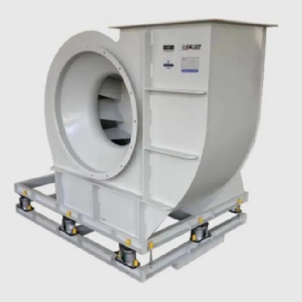
2. For site-assembled centrifugal fans, the machined surfaces on the base should be properly protected and should not have rust or damage. When placing the base on the foundation, it should be leveled using paired inclined shims.
3. The bearing housing should tightly fit the base, with longitudinal level deviation not exceeding 0.2/1000, measured with a level on the main shaft, and transverse level deviation not exceeding 0.3/1000, measured with a level on the horizontal mid-plane of the bearing housing.
4. Before scraping the bearing shells, the axis line of the rotor should be aligned with the casing axis line, simultaneously adjusting the gap between the impeller and the inlet and the gap between the main shaft and the rear side plate bearing hole of the casing to meet the specifications in the equipment technical documents.
5. During assembly of the main shaft and bearing shells, checks should be carried out according to the specifications in the equipment technical documents. The clearance between the bearing cover and the bearing shell should be maintained at 0.03 to 0.04 millimeters (measured by the outer diameter of the bearing shell and the inner diameter of the bearing housing).
6. When assembling the fan casing, the position of the casing should be aligned based on the rotor axis centerline, and the axial and radial gaps between the impeller inlet and the casing inlet should be adjusted to the range specified in the equipment technical documents. At the same time, check if the anchor bolts are securely fastened. If the equipment technical documents do not specify the gap values, the general axial gap should be 1/100 of the impeller outer diameter, and the radial gap should be uniformly distributed, with a value of 1.5/1000 to 3/1000 of the impeller outer diameter (for smaller outer diameters, take the larger value). During adjustment, strive to minimize the gap values to improve fan efficiency. When aligning the fan, the misalignment between the fan shaft and the motor shaft should not exceed 0.05 millimeters radially and should not exceed 0.2/1000 in inclination. For centrifugal fans with rolling bearings, the misalignment of the bearing holes on the two bearing frames can be determined after the rotor is installed, based on whether the rotation is smooth.
Zibo Hongcheng Fan Co., Ltd. specializes in the production of over 50 series and more than 600 specifications and models of fans. These products are widely used in industries such as mining, coal mines, oil fields, chemical plants, kilns, metallurgy, boilers, textiles, and building materials. Custom production and processing according to provided drawings are available. Welcome to contact us for cooperation.