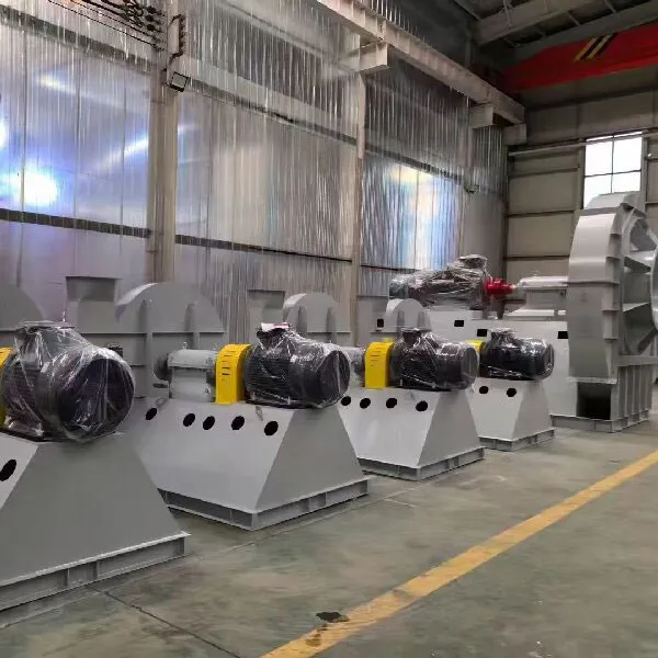
Installation and Commissioning
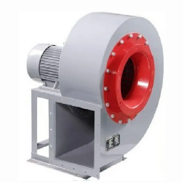
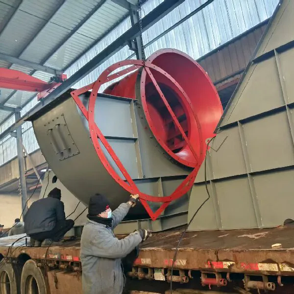
a) Equipment Foundation, Installation Conditions, and Technical Requirements: This series of fans does not require a special equipment foundation and can operate stably over long periods when placed on a relatively flat tunnel floor. For suspended installation, anchor bolts should be installed according to the positions of the top lifting ears of the fan, and connected using U-shaped lifting steel.
b) Commissioning Procedure, Methods, and Precautions: Remove the fan's collector and diffuser, open the explosion-proof wiring boxes at both ends of the motors, select suitable flame-retardant cables based on motor power, run the wires through the cable glands on the first and second-stage main units' casings, connect them to the motors via the explosion-proof wiring boxes, secure the wiring boxes by tightening the gland nuts, and After the fan installation and commissioning, the following requirements should be met:
c1. The radial clearance between the impeller and the casing should be uniform, ensuring it is within 0.15% to 0.35% of the impeller diameter;
c2. After assembly of Grade I and II fans, the spacing between the end faces of the hubs of Grade I and II should not be less than 9mm;
c3. The maximum output power of each motor shall not exceed 95% of its rated power;
c4. The rotation direction of the impeller must be consistent with the direction indicated on the casing;
c5. This series of fans must be managed and operated by designated personnel;
c6. The installation and usage location of this series of fans must comply with the relevant provisions of the 'Coal Mine Safety Regulations'.
d. Preparation before trial operation, trial operation
d1. Select suitable cables and dedicated switches;
d2. Connect according to the requirements of sub-clause b and properly connect the switch;
d3. Carefully check whether all connecting bolts of the impeller cover, motor fixing tube, and other parts are complete, secure, and reliable;
d4. Manually rotate both stages of the impeller, the turning should be flexible, without friction or jamming;
d5. Start one stage of the fan first, wait until it runs stably, then start the other stage, run for 20 minutes, stop the machine, and carefully check again whether the impeller cover, motor fixing tube, and other parts' connecting bolts are secure and reliable. Only after everything is accurate can long-term operation or standby begin.


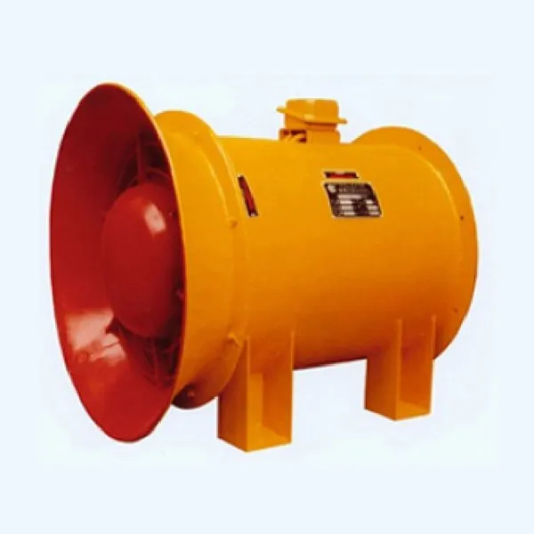
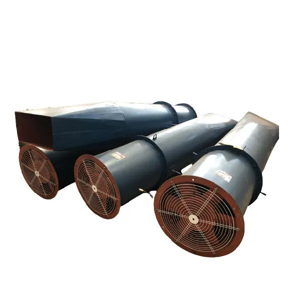
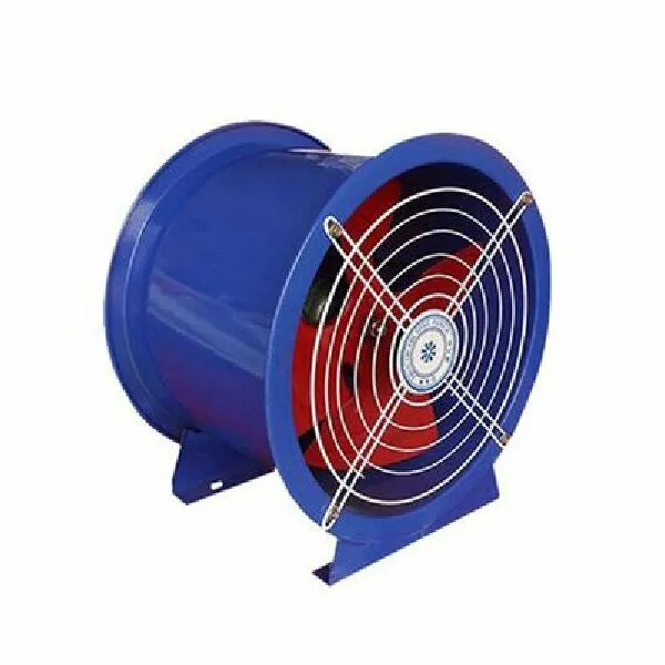
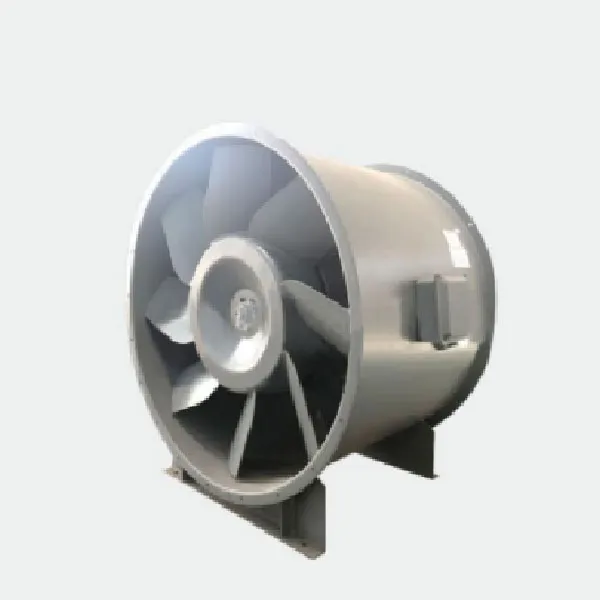
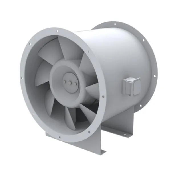
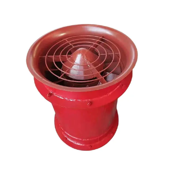
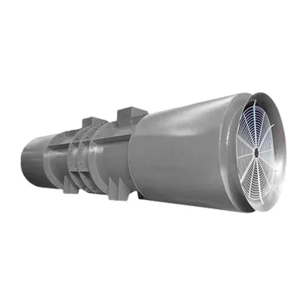
 explosion-proof pressure-injection counter-rotating axial flow local ventilation fan")
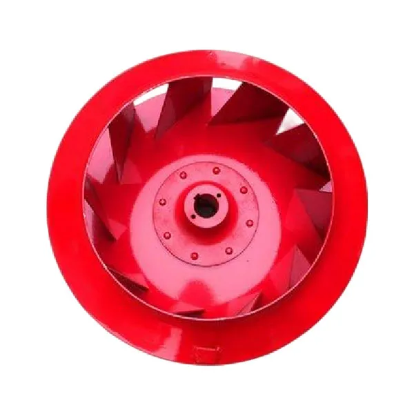
 explosion-proof pressure-injection counter-rotating axial flow local ventilation fan")
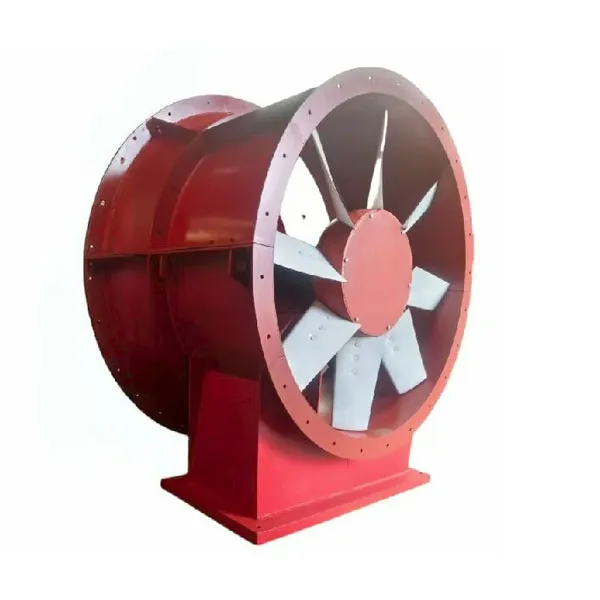
 explosion-proof pressure-injection counter-rotating axial flow local ventilation fan")
 explosion-proof pressure-injection counter-rotating axial flow local ventilation fan")