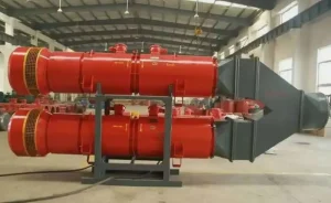
Tunnel axial flow fan, local ventilation fan for tunnels, SDF-NO10 2*55kw counter-rotating axial flow fan. Air volume: 670 – 1170 m³/H. Total pressure: 360 – 6160 pa. Rotational speed: 1450 r/min. Fan length: 4200 mm.
I. Introduction
The SDF series tunnel axial flow fans are local ventilation fans for tunnel areas. This product is manufactured in strict accordance with MT755-1997 “Technical Conditions for Counter-rotating Local Ventilation Fans”. This product is currently the most ideal tunnel ventilation equipment in both domestic and international markets.
II. Overview
a. Product features
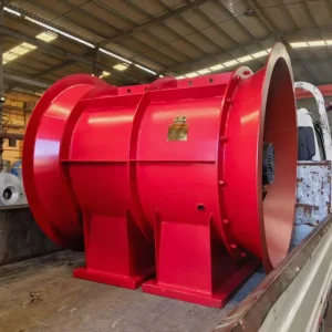
The SDF series tunnel axial flow fans for local ventilation have features such as a reasonable structure, complete specifications, high efficiency, obvious energy-saving effect, low noise, and long air supply distance. Depending on different ventilation resistance requirements, the entire machine can be used or used in stages, thereby reducing ventilation power consumption and saving energy. When the tunnel length is within 2000m, the fan can operate normally without moving, reducing workers’ labor intensity and saving ventilation time, making it an ideal equipment for local ventilation in coal mines. At the same time, it can also be used in metallurgy, non-ferrous metals, gold, chemical, shipbuilding and ceramic industries and other high-pressure ventilation scenarios. Its structural characteristics are mine explosion-proof type, counter-rotating, sound-absorbing, and axial flow type.
b. Main applications and applicable scope
This product is mainly used as a pressurizing local ventilation fan in coal mines, suitable for local ventilation in mining work areas and various chambers. It is also applicable to local ventilation scenarios in other mines and various tunnel ventilation scenarios.
c. Varieties and specifications
This product is a series product with complete specifications and varieties. Detailed information can be found in the FBD series of mine explosion-proof pressurizing counter-rotating axial flow local ventilation fan technical performance and external installation dimensions table (hereinafter referred to as Table 1).
e. Operating environment conditions
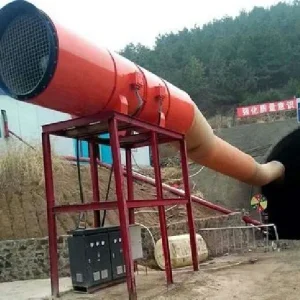
This product can be placed horizontally on the bottom of the tunnel or hung on the tunnel wall. When placed on the bottom, the suction port (collecting device end) of the fan must not be immersed in water or cement. The gas temperature of the operating environment should be -20 to 50℃, and the altitude should not exceed 1000m. The rated frequency of the used power supply is 50Hz, and the rated voltage is 380V/660V or 660V/1140V of any level.
f. Working conditions
This product has a gas dust content of no more than 200mg/m3. It should be installed in the intake air flow of the coal mine with a methane concentration less than 1%. When the methane concentration exceeds 1%, the power supply should be immediately cut off.
g. Impact on the environment and energy
This product has no pollution to the environment and is a highly energy-efficient product.
h. Safety
This product is designed reasonably and has a mine explosion-proof certificate and “MA” safety mark approval certificate. The accompanying motor also has these two certificates, belonging to explosion-proof safety products.
III. Structural features and working principle
a. Overall structure, working principle, and working characteristics
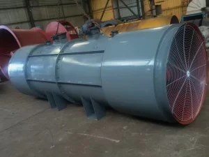
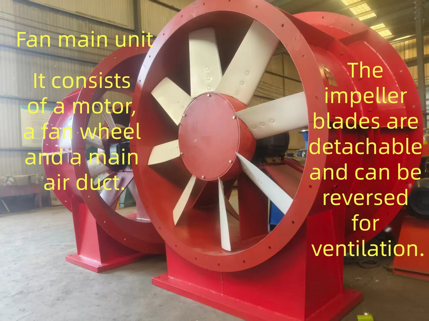
This product has two impellers installed close to each other, driven by two motors to rotate in opposite directions. The airflow enters the first-stage impeller along the axial direction, and the direction of the accelerating airflow is deflected, flowing into the second-stage main unit. After being accelerated by the second-stage impeller again, the airflow direction is deflected in the opposite direction and is discharged from the diffuser end along the axial direction.
b. Main Components, Function and Working Principle
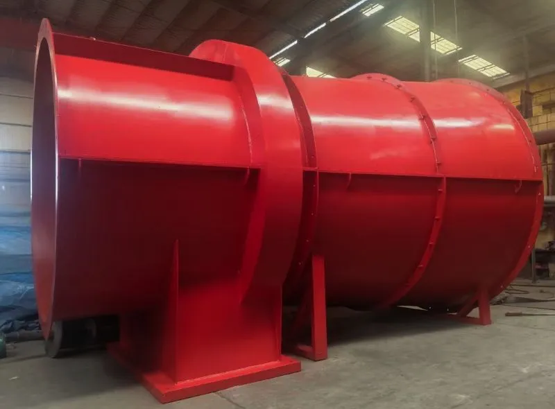
As shown in the figure, this product consists of four main components: the collector, the first-stage main unit, the second-stage main unit, and the diffuser. The collector is composed of an arc-shaped collector port and a guide cover. Its main function is to reduce the local resistance loss of the airflow and create favorable intake conditions for the first-stage main unit. The first-stage main unit is composed of the first-stage casing, the first-stage impeller, and the first-stage motor, etc. The casing is the main bearing body of the unit, mainly ensuring the normal operation of the impeller and the motor, and also serving as a muffler. The impeller is the core component of the first-stage main unit for generating airflow, and the motor is the power component that makes the impeller rotate. The working principle is that the airflow entering from the collector end flows axially into the first-stage impeller, is accelerated, and then its direction changes before flowing into the second-stage main unit. The second-stage main unit is composed of the second-stage casing, the second-stage impeller, and the second-stage motor, etc. The casing and motor of the second-stage have the same main functions as the first-stage. The impeller of the second-stage is the core component for generating airflow in the second-stage main unit. The working principle is that the airflow flowing out from the first-stage impeller flows into the second-stage impeller with a deflection, is accelerated again, and then its direction changes in the opposite direction, flows axially into the diffuser, and the diffuser is composed of a diffusion cylinder and a guide cover, mainly serving to reduce the local resistance loss at the outlet of the airflow, improving the effective working capacity of the fan, and the airflow flows axially out of the fan through it, and also serving as a rear muffler.
c. Technical Characteristics
a. Main Performance
This series of fans have main performance such as explosion-proof safety, noise reduction, stable operation, smooth characteristic curve, and wide efficient range.
b. Main Parameters
The main technical performance parameters of this series of fans include: air volume Q, total pressure P, total pressure efficiency η, noise (A-weighted sound level) LSA, and rotational speed n, etc. The highest efficiency of this series of fans is 86%, the highest noise does not exceed 85 dB(A), and the detailed parameters of the series fans can be found in Table 1.
c. Installation and Commissioning
a. Equipment Foundation, Installation Conditions and Installation Technical Requirements
This series of fans do not require a special equipment foundation. They can be placed on a relatively flat roadway floor to operate stably for a long time. When installed in a suspended manner, anchor rods should be driven at the position of the top lifting ears, and the U-shaped steel connection should be connected well.
b. Commissioning Procedure, Method and Precautions
Remove the collector and diffuser of the fan, open the explosion-proof junction box of the two ends of the motor, select the appropriate flame-retardant cable according to the motor power, thread the cable from the threading box on the casing of the first and second stages, connect it to the motor through the explosion-proof junction box, install the junction box and tighten the compression nut to secure the cable, and then connect the collector and diffuser. It should be noted that the junction box of the motor is explosion-proof, and as long as it is opened once, before re-connecting, the joint surface must be coated with industrial shellac or 107 anti-rust oil to ensure the explosion-proof performance of the motor.
Check whether the connecting bolts of each part are complete and reliable. Manually rotate the two impellers to ensure that they are flexible. Then, you can carry out trial operation and commissioning.
c. Acceptance Test Items, Methods and Criteria after Installation and Commissioning
After the installation and commissioning of the fan, the following requirements should be met:
C1. O le Radial kilia i le va o le impeller ma e tatau ona toniga le toniga, mautinoa o le 0.15% i le 0..35% o le Impeller shimeter;
c2. After the assembly of the first and second-stage wind turbines, the distance between the end faces of the first and second-stage hubs should not be less than 9mm;
c3. The maximum output power of each motor should not exceed 95% of its rated power;
c4. The rotation direction of the impeller must be consistent with the direction indicated by the rotation mark on the casing;
c5. This series of fans must be managed and operated by a dedicated person;
c6. The installation and use location of this series of fans must comply with the relevant provisions of the “Coal Mine Safety Regulations”.
d. Preparation before trial operation, trial operation d1. Select the appropriate cables and dedicated switches;
d2. Connect and install the switches as per the requirements of this item b;
d3. Carefully check whether all the connection bolts for the impeller cover, motor fixing cylinder and other parts are complete, firm and reliable;
d4. Manually rotate the two-stage impeller and ensure that the rotation is smooth, without friction or jamming;
d5. Start any one of the fans first, wait for it to run stably, then start the other fan, run for 20 minutes and then stop. After that, carefully check whether all the connection bolts for the impeller cover, motor fixing cylinder and other parts are firm and reliable. Once everything is correct, the fan can be operated for a long time or kept for use.
Six, Button Instructions for the Fan Frequency Control Cabinet
1. Function: Controls the on-off of the main power supply of the control cabinet, serving as the “main switch” for the fan power supply, and also has overload and short-circuit protection functions. – Operating Instructions:
– Close: Move the switch handle from the “off (OFF)” position to the “on (ON)” position, and confirm the locking with a “click” sound. At this point, the main power supply is connected.
– Open: In emergency situations or when stopping, directly move the handle to the “off (OFF)” position to cut off the main power supply.
– Note: Before operating, ensure there are no obvious faults in the cabinet. After closing, the voltmeter should show voltage.
2. Start/Stop Switch (Operation Button)
– Function: Directly controls the start and stop of the fan, divided into local manual operation and remote control modes (some cabinets have a mode switching switch).
– Type and Operation:
– Button type: Press the green “start (START)” button, the contactor is attracted, the fan starts; press the red “stop (STOP)” button, the contactor is disconnected, the fan stops.
– Note: Before starting, confirm that the fan is not stuck or noisy. After stopping, if maintenance is required, disconnect the main power switch and hang a sign.
3. Acceleration/Deceleration Switch
– Acceleration Button: When pressed, the frequency of the fan motor’s operation is increased through the frequency converter, causing the rotational speed to rise and the air volume/fine pressure to increase.
– Deceleration Button: When pressed, the motor’s operating frequency is reduced, causing the rotational speed to decrease and the air volume/fine pressure to decrease.
The combination of these two can achieve continuous or staged adjustment of the fan’s rotational speed, which is suitable for scenarios where the air volume needs to be dynamically adjusted according to the working conditions (such as ventilation systems, industrial dust removal, etc.).
4. Common Switch Status Indicators
– Operation Indicator Light: When lit, it indicates that the fan is in operation.
When operating the switch of the fan start cabinet, strictly follow the equipment manual and safety regulations. Non-professionals are prohibited from operating without authorization. In case of a fault, contact an electrician or maintenance personnel for handling promptly.
5. Detailed instructions for starting the fan:
1. Pre-start inspection (key step)
1. Equipment status check:
– Confirm that the fan impeller is not blocked, the blades are not damaged, the air duct is not clogged, and the connecting bolts are tightened.
– Check if the circuit breakers and terminal blocks inside the frequency conversion start-up cabinet are loose, and ensure that the cabinet door is tightly closed without any foreign objects or water accumulation.
2. Safety preparations:
– Ensure that there are no personnel working in the operation area, the fan outlet is not blocked, and hang a warning sign reading “Starting, Be Safe” (if necessary).
– Operators must confirm that they are familiar with the location of the stop button in case of an emergency.
II. Power Supply Operation
1. Turn on the main power switch:
– Locate the main power circuit breaker (the main switch) inside the cabinet. Rotate the handle from “OFF” to “ON”, and hear the “click” sound before locking it. At this point, the main power indicator light (such as “Power Indicator”) will light up.
2. Turn on the control power switch:
– Close the control circuit breaker (small circuit breaker or knob), and move it to the “ON” position. The control circuit is energized, and the operation panel buttons and display (if any) will be activated.
III. Mode Settings (Choose according to requirements)
The frequency conversion start-up cabinet usually has modes such as “local manual” and “remote control”. Before starting, it is necessary to confirm the mode:
– Local Manual Mode (On-site Operation):
Switch the mode selection switch (such as the “Local/Remote” knob) to “Local” or “Manual”. At this point, you can directly control it through the on-site buttons.
– Remote Control Mode (Control by External Signal):
If you need to start using PLC or the central control system, switch to “Remote”. The start will be triggered by an external signal (make sure the remote signal is normal before proceeding).
4. Start the fan
(1) Local manual startup (the most commonly used)
1. Press the “Start” button:
Press the green “Start (START)” button on the cabinet panel. The frequency converter begins to output voltage, and the motor drives the fan to start slowly (soft start with frequency conversion, the speed gradually increases from 0).
– During the start-up process, observe the display (if any): the frequency gradually increases from the initial value (such as 0 Hz), and the speed also increases synchronously, with no abnormal noise.
– If the start fails (the fault code appears on the frequency converter display panel), immediately press the “Stop” button, and check for overload, phase missing, or motor faults before trying again.
2. Confirm the initial speed:
After starting, the fan defaults to running at the initial frequency (such as 50 Hz or the preset minimum frequency), or maintains the speed before the last shutdown. You can observe the current status using a speed meter or frequency meter.
(2) Speed control operation (if you need to adjust the air volume)
1. Speed Adjustment:
Press the “Acceleration (ACCEL)” button or the up arrow key to gradually increase the frequency (e.g. from 30Hz to 50Hz), the rotational speed rises, the air volume increases. Release the button to lock the current rotational speed.
2. Deceleration Adjustment:
Press the “Deceleration (DECEL)” button or the down arrow key to decrease the frequency (e.g. from 50Hz to 20Hz), the rotational speed decreases, the air volume decreases. Release to maintain the current rotational speed.
3. Note:
– Speed adjustment should be carried out slowly. The single adjustment range should not be too large (e.g. increase or decrease by 5Hz each time). Avoid fan vibration or motor overload.
– The lower limit of rotational speed is limited by the parameters of the frequency converter (usually not lower than 10-15Hz). Too low a rotational speed may cause poor heat dissipation of the motor.
When starting the mine-use counter-rotating fan, the rotation direction of the fan impeller must be consistent with the arrow on the fan housing. When two motors are started simultaneously, the interval should not exceed 30 seconds. The two motors should operate at the same speed. Any one of them can be started and operated independently.
V. Post-Startup Inspection
– Run for 1-2 minutes. Listen for any abnormal sounds from the fan and motor (such as rubbing or screeching noises). Touch the motor casing and check for any abnormal overheating (temperature ≤ 70℃, refer to the equipment manual for specific details).
– Observe the display of current and voltage (if any): The current is stable with no significant fluctuations and there is no overload alarm.
VI. Emergency Situation Handling
If any abnormalities occur during startup or operation (such as severe vibration, smoke emission, or strange odors), immediately press the red “Stop” button. The frequency converter will be forcibly powered off and the fan will stop running. After the fault is resolved, rotate the emergency stop button clockwise to reset, and then restart.
Notes for Attention
– It is strictly prohibited to frequently switch the “start/stop” function before the fan has completely stopped, as this may cause motor shock and damage.
– Non-professionals are forbidden to open the cabinet door to operate the internal components. During maintenance, the main power supply must be disconnected and a sign must be hung.
– For the first startup or restart after a long period of shutdown, it is recommended to perform a jog start first (press “start” and immediately press “stop”). Check whether the impeller rotation direction is correct (consistent with the arrow mark on the casing).
Operate strictly in accordance with the equipment manual and on-site procedures to ensure the safe and efficient operation of the rotary axial flow fan.
VIII. Use, Operation and Maintenance
a. Before using the fan, recheck whether all the fixed and connecting bolts of each part are loose, complete, firm and reliable;
b. Rotate the two-stage impellers by hand. The rotation should be flexible without any friction, impact, abnormal noise or other sounds;
c. Test run by single-point operation, check whether the rotation direction of the impeller is correct, and the rotation direction of the impeller should be consistent with the arrow on the fan housing;
d. During operation, frequently check whether the sound is normal and whether the connections are loose;
e. This series of fans are generally inspected once every 6 months, and all components of the machine should be checked;
f. When this series of fans are not in use, they should be placed in an area with air circulation and dryness to prevent moisture, corrosion and other losses.
IX. Fault Analysis and Elimination
The analysis and elimination methods of faults are shown in Table 2.
Fault Analysis and Elimination Methods Table 2
Fault Phenomenon Cause Analysis Elimination Method Remarks
There are friction sounds and impact sounds. The impeller is loose or the motor is loose, deviating from the normal working position. Re-position it, tighten the bolts of the impeller cover or the motor fixing cylinder. If you find that the bolt is damaged, replace it immediately.
There is abnormal noise. The motor bearings are worn out and lack lubricating oil. Remove the motor, replace the bearings and add lubricating oil.
The vibration of the casing suddenly increases. The impeller is covered with dust and dirt, causing it to lose balance or the motor bearings are severely lacking in lubricating oil. Stop the machine, clean the surface of the impeller or clean the motor bearings and add lubricating grease.
The current suddenly increases. There are foreign objects adhering, blocking the intake port of the fan or the wind tube is bent or jammed. Stop the machine and remove the foreign objects from the intake port or straighten the wind tube.
X. Transportation and Storage
a. Precautions for吊装 and transportation
When吊装, the two lifting lugs of the fan should be used for lifting. Directly tying the fan with steel wire ropes is not allowed.