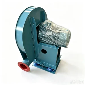
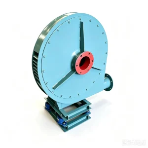
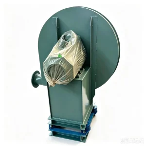
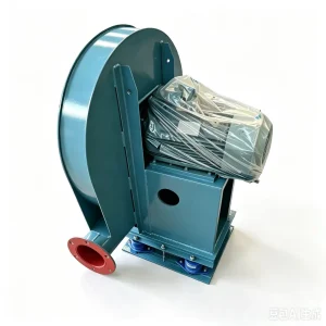
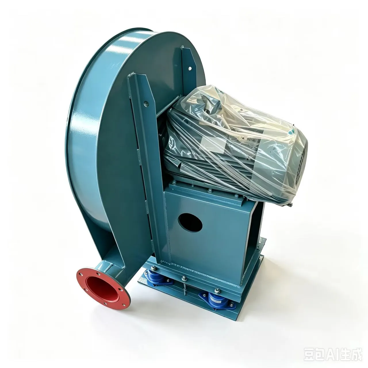
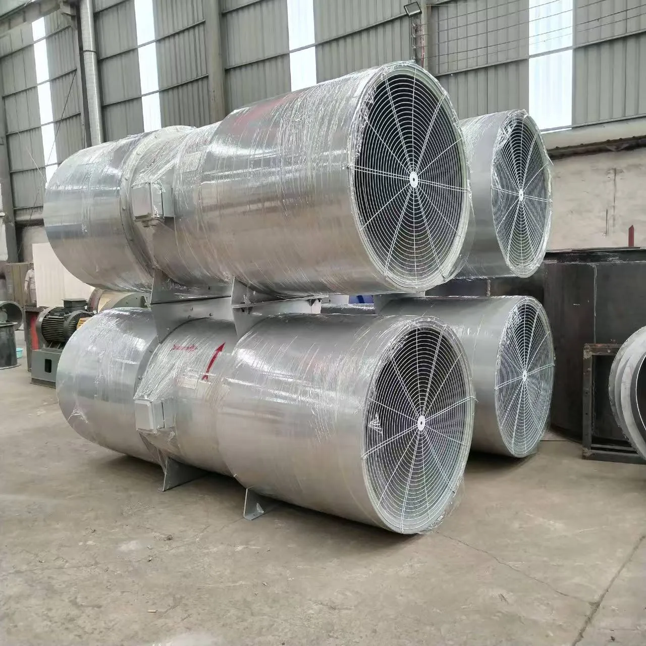
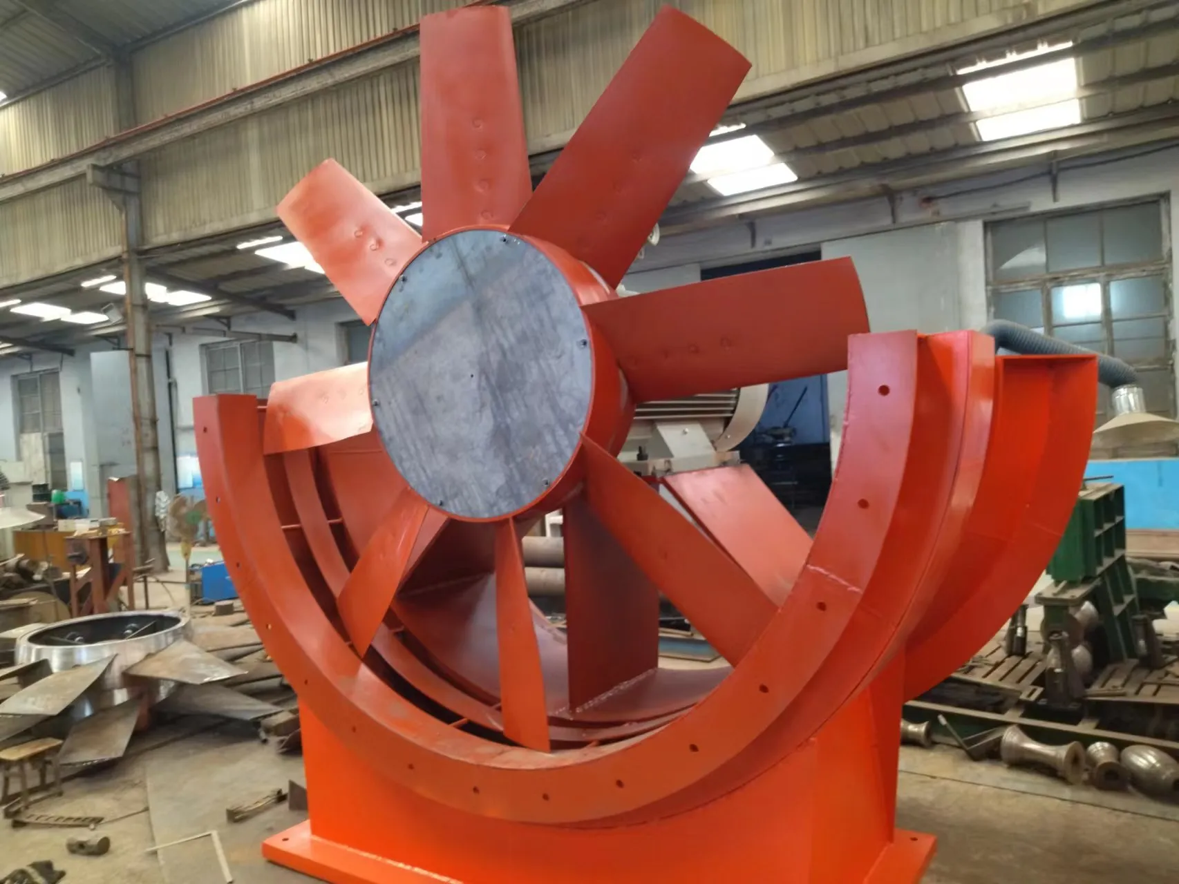
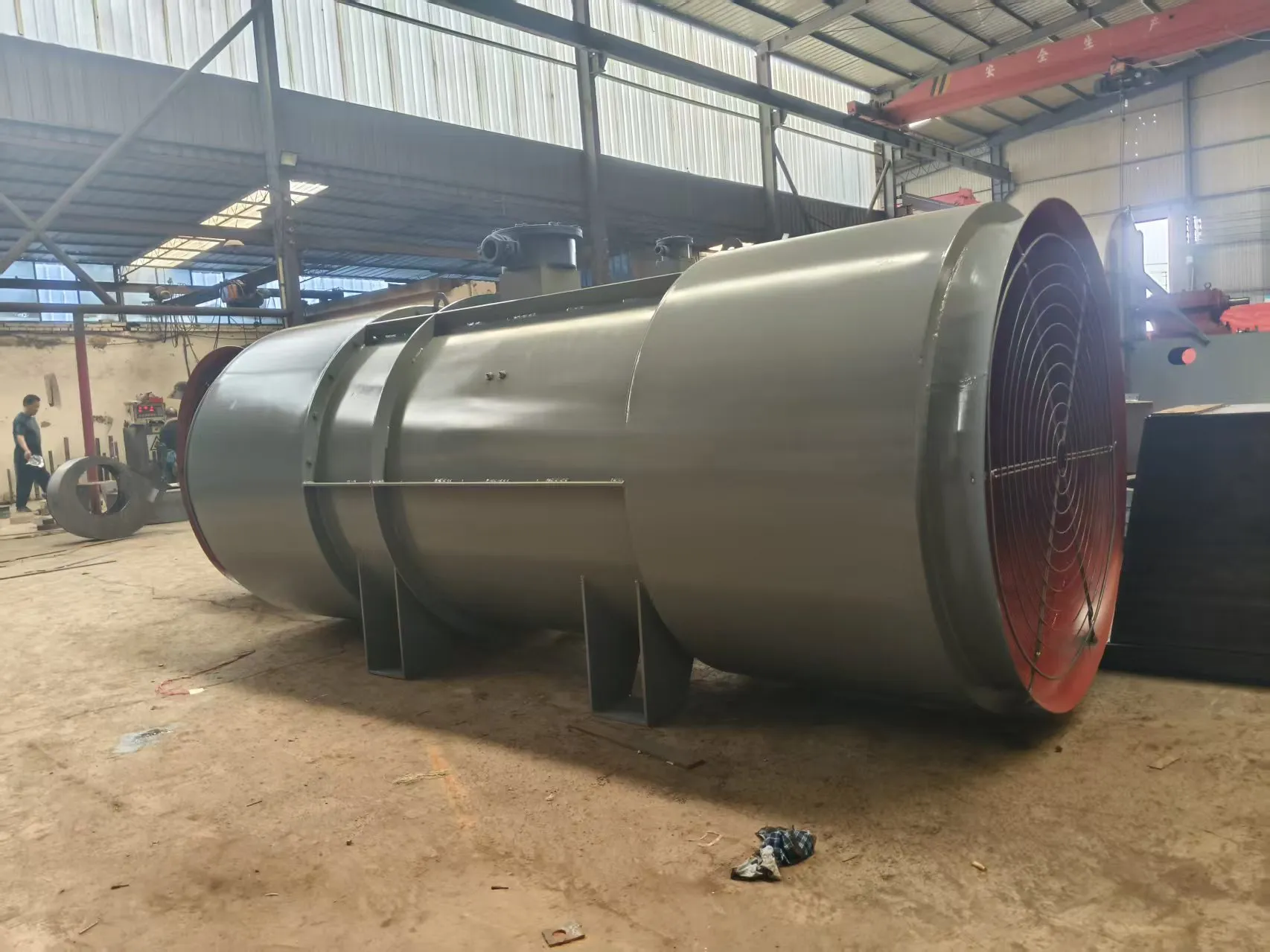
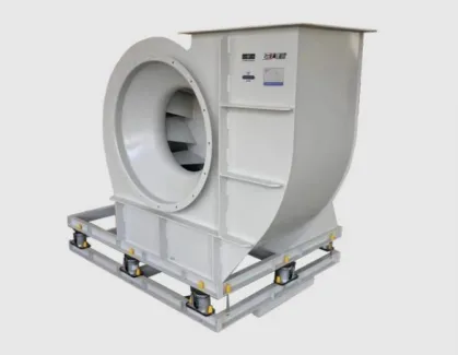
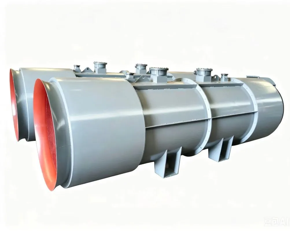
Industrial blowers 9-19High-Pressure Centrifugal Fan adopt the structure where the motor is directly connected to the impeller. This structure is simple, easy to install, and occupies less space. This series of centrifugal blowers can also be made with belt drive or coupling drive. They are mainly used in industrial forced ventilation fields such as boilers, kilns, and cement plants.
Industrial blowers – High-Pressure Centrifugal Fan
1. The fan adopts a single suction design. The model ranges from 2.8 to 16#.
2. Each type of fan can be made in two forms: left-handed or right-handed. From the side of the motor, the impeller rotates clockwise, which is called a right-handed fan and is denoted by “right”; if the impeller rotates counterclockwise, it is called a left-handed fan and is denoted by “left”.
3.Industrial blowers The high-pressure centrifugal The outlet position of the fan is determined by the outlet angle of the housing. The 8-09 high-pressure centrifugal fan has a rectangular outlet, and it can also be customized as a circular outlet according to customer requirements.
4. The transmission methods of the fan include A type: motor direct connection; C type: belt drive; D type: coupling drive.
9-19High-pressure centrifugal fan fault repair
The wear of the transmission parts of C-type and D-type centrifugal fans is a common equipment problem, including wear at the bearing position and bearing chamber of the fan, corrosion of the impeller causing vibration issues. For the above faults of centrifugal fans, traditional methods for repairing the transmission parts include welding, thermal spraying, brush plating, or replacing new bearings and transmission components. The vibration repair method for the impeller includes sending the small fan back to the factory for dynamic balance correction of the impeller, or performing on-site dynamic balance correction on the fan. Or replacing the impeller of the same model.
9-19Installation Matters for High-Pressure Centrifugal Fans
- For the installation of the entire centrifugal fan unit, it should be placed directly on the foundation and leveled using pairs of inclined shims.
- For the centrifugal fan assembled on-site, the machined surfaces on the base should be properly protected and should not be subject to rust or operation. When placing the base on the foundation, use pairs of inclined shims for leveling.
- The bearing seat and base should be closely joined. The longitudinal levelness should not exceed 0.2/1000, and the measurement should be conducted on the main shaft using a level gauge. The lateral levelness should not exceed 0.3/1000, and the measurement should be conducted on the horizontal center plane of the bearing seat.
- Before scraping the bearing bush, the rotor axis line and the casing axis line should be aligned first. At the same time, adjust the gap between the impeller and the air inlet and the gap between the main shaft and the rear side plate shaft hole of the casing to meet the requirements specified in the equipment technical documents.
- During the assembly of the main shaft and the bearing bush, check according to the equipment technical documents. The interference between the bearing cover and the bearing bush should be 0.03 to 0.04 millimeters (measure the outer diameter of the bearing bush and the inner diameter of the bearing seat).
- When assembling the fan casing, align the position of the casing with the rotor axis line as the reference and adjust the axial and radial clearances between the impeller air inlet and the casing air inlet to within the range specified in the equipment technical documents. At the same time, check if the anchor bolts are tightened. If there are no specific regulations in the equipment technical documents, generally, the axial clearance should be 1/100 of the impeller outer diameter, and the radial clearance should be evenly distributed, with a value ranging from 1.5/1000 to 3/1000 of the impeller outer diameter (the larger value is taken for the smaller diameter). Try to make the clearance value smaller to improve the efficiency of the fan.
- During the alignment of the fan, the different axis degree of the fan shaft and the motor shaft: the radial positioning deviation should not exceed 0.05 millimeters, and the inclination should not exceed 0.2/1000.
- For centrifugal fans with rolling bearings, the different axis degree of the bearing holes on the two bearing brackets can be determined after the rotor is installed, by checking for smooth rotation.