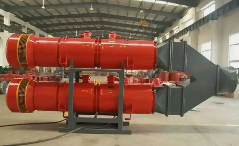
The GY6-41 boiler forced and induced draft fan is designed for industrial boilers with a capacity of 0.5t/h to 10t/h that burn various fuels and are equipped with dust and smoke elimination devices. It is a new series of low-noise fans with a total pressure efficiency higher than 80%. As long as the intake conditions are similar and the performance is comparable, they can all be used. The GY6-41 fan is the successor to the boiler forced and induced draft fans.
The design features of the GY6-41 boiler forced draft and induced draft fans are as follows: Selecting the appropriate fan type, reasonable fan operating conditions, optimizing the flow pattern, rationally organizing the air source, carefully designing the blade shape, appropriately reducing the fan speed, improving the volute design, purifying the incoming flow and minimizing secondary flow losses, etc. The finite difference method is used to calculate the inlet and wheel cover profile of the fan, and the smooth and uniform flow at the inlet of the impeller is taken as the optimization criterion for the inlet optimization design. Combined with the original fan impeller, volute and other optimization design methods, an integrated optimization design program for the impeller, volute and inlet is developed to obtain the aerodynamic sketch curve. Practice has proved that it can not only ensure the air pressure and air volume, but also ensure better efficiency, lower specific noise and smaller fan size.
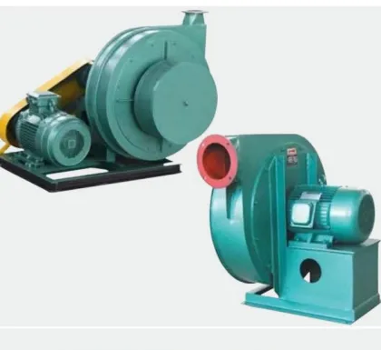
The type of GY6-41 boiler forced draft and induced draft fans
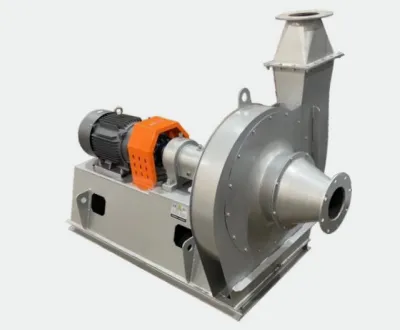
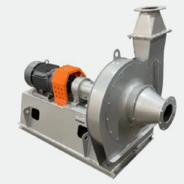
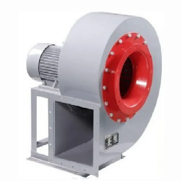
1. The transmission methods of the fans are as follows: C type – belt drive; D type – coupling drive.
2. The induced draft fan can be made in two types: right rotation and left rotation. When viewed from the motor side, if the impeller rotates clockwise, it is called a right rotation fan; if the impeller rotates counterclockwise, it is called a left rotation fan.
3. The position of the air outlet is indicated by the angle of the air outlet of the casing.
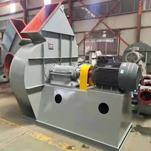
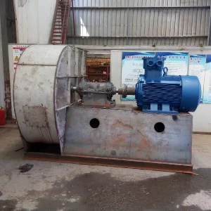
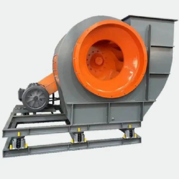
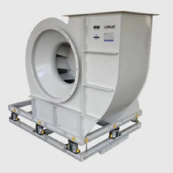
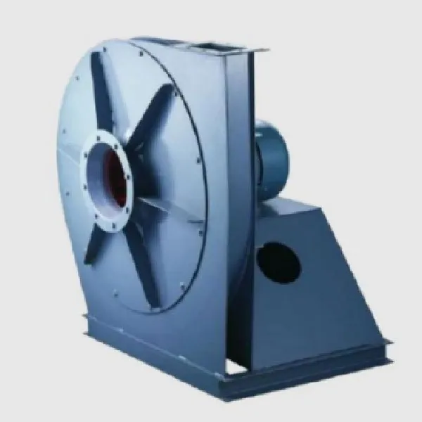
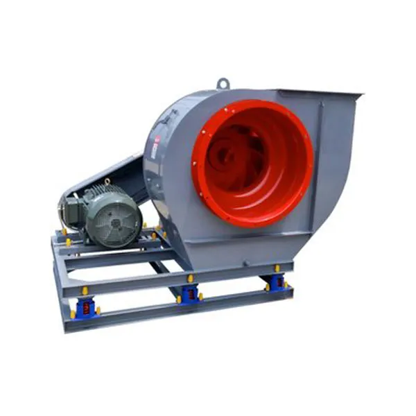
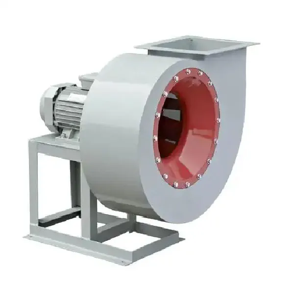
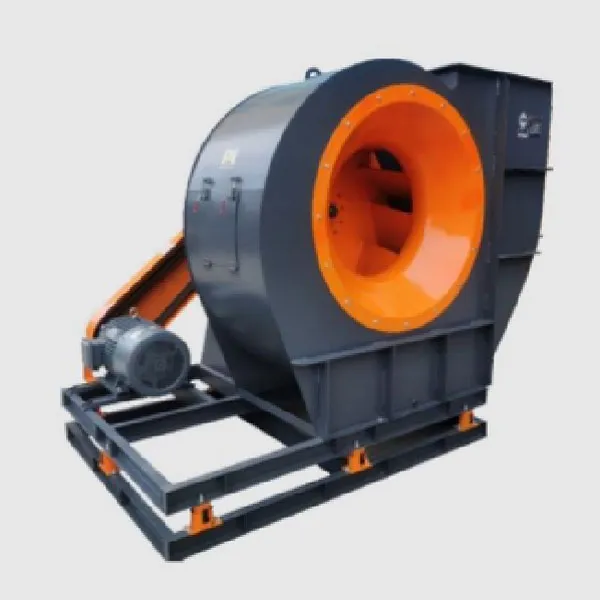
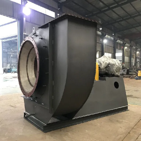
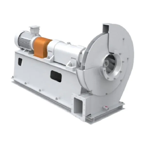
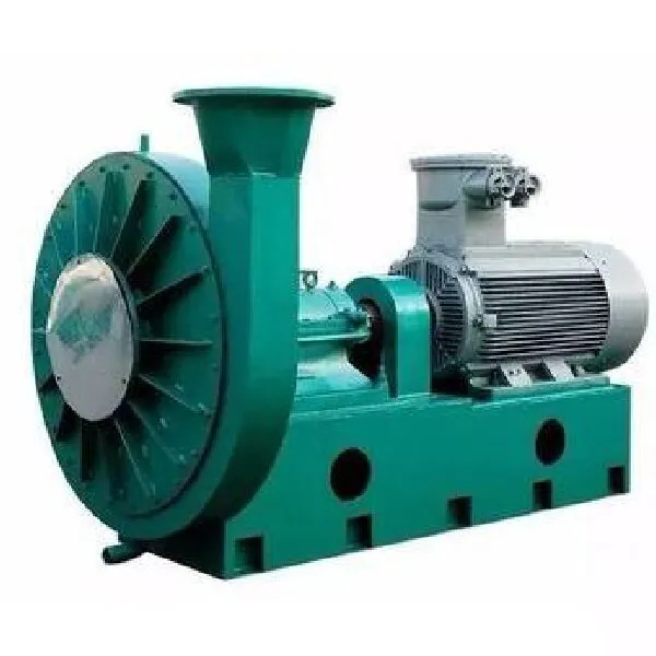
The structure of the GY6-41 boiler forced draft and induced draft fan
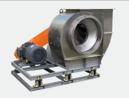
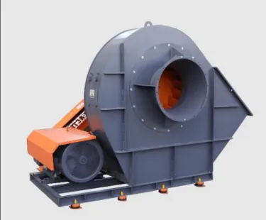
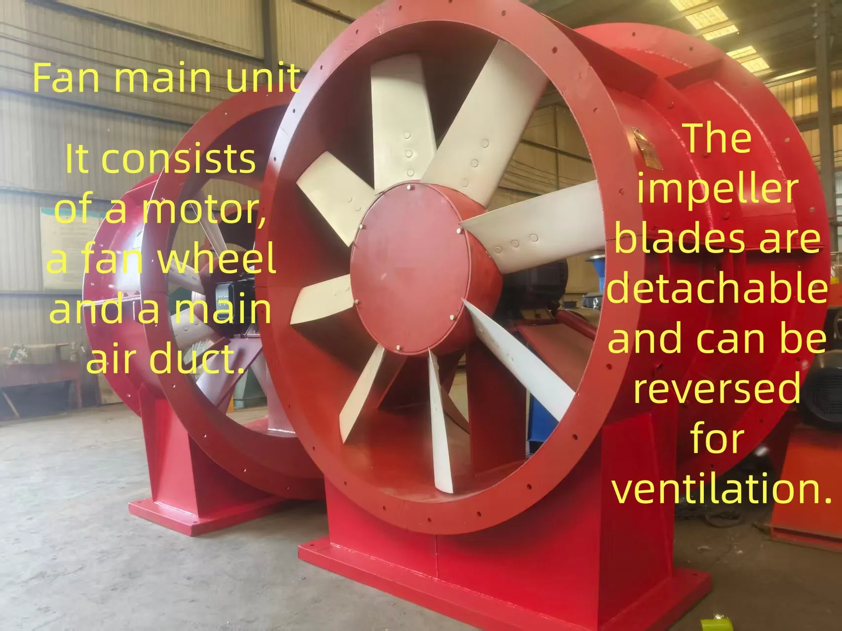
It is composed of the casing, air inlet, impeller, integral frame, transmission part, regulating door (according to customer requirements) and motor, etc.
Casing: Made of steel plate, it is firm and reliable.
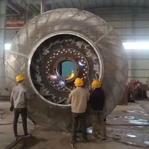
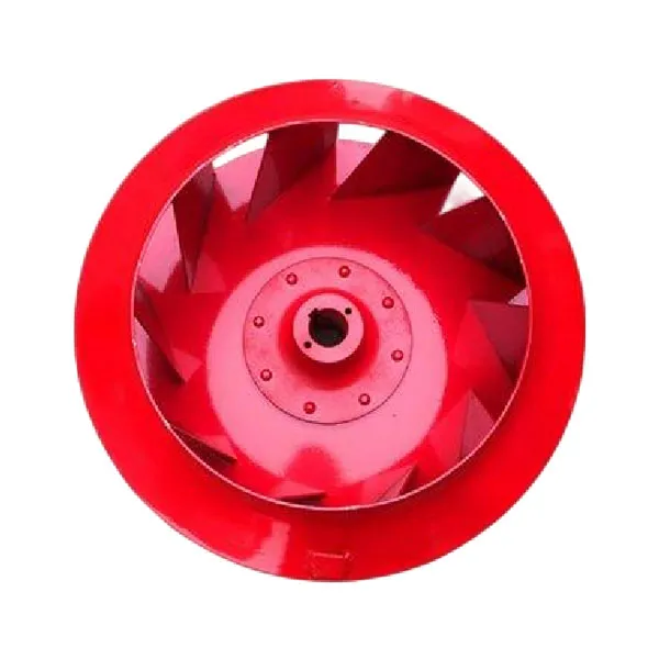
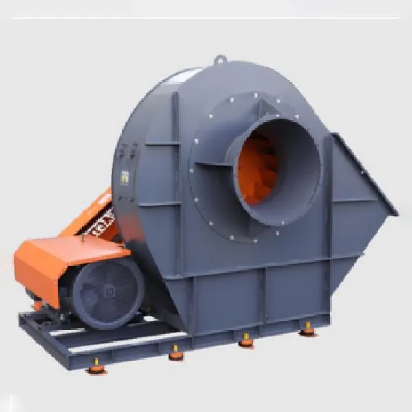
Impeller: Composed of 16 straight plate blades, a curved front disk and a flat back disk welded together. It should have undergone static and dynamic balancing to ensure smooth rotation of the fan and good performance.
Transmission part: Composed of the main shaft, bearing box, rolling bearings and pulley (or coupling).
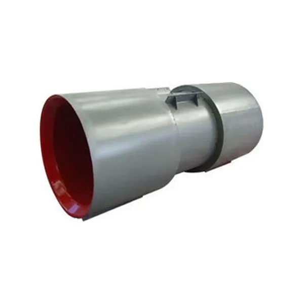
Air inlet: Welded from steel plates into a conical shape, it is a convergent streamlined integral structure. It is installed on the side of the fan, and the cross-section in the axial direction is curved, which enables the gas to enter the impeller smoothly with minimal loss.
Regulating door: Installed in front of the air inlet. Under the condition that the fan speed (pressure) remains unchanged, it can adjust the size of the air volume.
Common Fault Repair of GY6-41 Boiler Forced and Induced Draft Fans
Wear of the transmission parts of B, C, and D type centrifugal fans is a common equipment problem, including wear of the fan bearing position and bearing housing, and vibration problems caused by corrosion of the impeller. For the above-mentioned faults of centrifugal fans, traditional methods for repairing the transmission parts include surfacing welding, thermal spraying, and electroplating, or replacing new bearings and transmission groups. For impeller vibration repair, small fans can be returned to the factory for impeller dynamic balance correction, and for fans above 12#, on-site dynamic balance correction can be performed. Or, the same model impeller can be replaced.
Installation Matters of GY6-41 Boiler Blower and Inducer
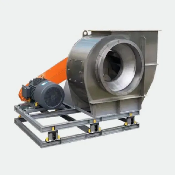
1. The installation of the complete centrifugal fan unit should be directly placed on the foundation and leveled with pairs of shims.
2. For on-site assembled centrifugal fans, the machined surfaces on the base should be properly protected and should not be rusted or damaged. When placing the base on the foundation, it should be leveled with pairs of shims.
3. The bearing housing and the base should be closely joined, with the longitudinal non-levelness not exceeding 0.2/1000. This can be measured with a level on the main shaft. The transverse non-levelness should not exceed 0.3/1000, which can be measured with a level on the horizontal mid-plane of the bearing housing.
4. Before scraping the bearing bush, the axis of the rotor and the casing should be aligned, and the gap between the impeller and the air inlet and the gap between the main shaft and the rear side plate bearing hole of the casing should be adjusted to meet the requirements specified in the equipment technical documents.
5. When assembling the main shaft and the bearing bush, the requirements specified in the equipment technical documents should be followed for inspection. There should be an interference fit of 0.03 to 0.04 mm between the bearing cover and the bearing bush (measured by the outer diameter of the bearing bush and the inner diameter of the bearing housing).
6. When assembling the fan casing, the position of the casing should be aligned with the rotor axis as the reference, and the axial and radial clearances between the impeller air inlet and the casing air inlet should be adjusted to the range specified in the equipment technical documents. At the same time, check if the anchor bolts are tightened. If the equipment technical documents do not specify the clearance values, generally, the axial clearance should be 1/100 of the impeller outer diameter, and the radial clearance should be evenly distributed, with a value of 1.5/1000 to 3/1000 of the impeller outer diameter (for smaller outer diameters, take the larger value). During adjustment, strive to keep the clearance values as small as possible to improve the fan efficiency.
7. When aligning the fan, the misalignment between the fan shaft and the motor shaft: the radial displacement should not exceed 0.05 mm, and the inclination should not exceed 0.2/1000.
8. For centrifugal fans with rolling bearings, the misalignment of the bearing holes on the two bearing frames can be checked after the rotor is installed, with smooth rotation as the standard.
Debugging Method for GY6-41 Boiler Blower and Inducer
Centrifugal fans are complex devices mainly composed of an air inlet, air valve, impeller, motor, and air outlet. The performance of centrifugal fans varies under different conditions. Therefore, if the operation status of different parts is not uniform, the performance of the centrifugal fan will be affected. To debug the centrifugal fan to its best state, multiple aspects can be considered.
1. Centrifugal fans can be started at full voltage or reduced voltage. However, it should be noted that the current at full voltage start-up is approximately 5 to 7 times the rated current. The starting torque at reduced voltage is proportional to the square of the voltage. When the grid capacity is insufficient, reduced voltage start-up should be adopted.
2. During the test run of the centrifugal fan, carefully read the product manual to check if the wiring method is consistent with the wiring diagram. Also, carefully check if the working voltage supplied to the fan meets the requirements, and whether there is a phase loss or phase sequence error in the power supply. Verify if the capacity of the electrical components is in line with the requirements.
3. At least two people should be present during the test run. One person controls the power supply, and the other observes the fan’s operation. If any abnormal phenomena are detected, stop the machine immediately for inspection. First, check if the rotation direction is correct. After the centrifugal fan starts running, immediately check if the currents of each phase are balanced and if they exceed the rated current. If any abnormality is found, stop the machine for inspection. After running for five minutes, stop the machine to check if there are any abnormal phenomena. Confirm that there are no abnormalities before restarting the machine.
4. When testing a dual-speed centrifugal fan, start at low speed first to check if the rotation direction is correct. When starting at high speed, wait until the fan has completely stopped before starting again to prevent reverse rotation at high speed, which may cause the switch to trip and damage the motor.
5. Once the centrifugal fan reaches its normal operating speed, measure the input current to ensure it is within the normal range. The operating current of the centrifugal fan should not exceed its rated current. If the operating current exceeds the rated current, check if the supplied voltage is normal.
6. The motor power required for a centrifugal fan refers to the power needed when the fan and fan box are operating at full air inlet. If the fan operates with the air inlet fully open, there is a risk of motor damage. During the test run of the fan, close the valve on the inlet or outlet pipe of the fan. After the fan starts running, gradually open the valve until the desired operating condition is reached, and pay attention to whether the operating current exceeds the rated current.
By strictly following the above debugging methods, the efficiency of the centrifugal fan can be made to exceed 98%.